QuickSilver cartridge for PCjr - A look at the BIOS patches it includes
Introduction
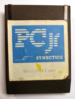
The QuickSilver cartridge sold PC Enterprises significantly speeds up a PCjr's boot sequence, hence its name. According to the manual, there are the 3 things this cartridge does:- Quicker (less thorough) memory test (The main time saver)
- No beep during POST, unless there was an error. (This saves times too, the computer does nothing during the beep!)
- Int9 keyboard compatibility fix (makes it act like it does on a PC)
I read somewhere that the original cartridge only replaces parts of the BIOS, presumably using address decoding logic to take over the bus when specific address ranges are accessed. This seems to make sense, as simply bundling a 64 kB ROM containing (except for a few tweaks) an almost identical copy of IBM's copyrighted BIOS may have not been exactly legal. But this could also mean a ROM smaller than 64 kB could be used to save costs too. (I have never looked inside a QuickSilver cartridge, so I don't know if that's the case...)
Comparing the normal and patched BIOS
Writing a small program to dump the contents of the BIOS to a file on a PCjr with and without a QuickSilver cartridge results two almost identical 64 kB files.I was wondering how substantial the BIOS modifications made by the cartridge were, so I compared a pristine BIOS dump (SYSTEM.ROM) with a dump made with the cartridge inserted (QUIKSILV.ROM).
On a Linux system, I used the hexdump to convert those to a human-readable hex dump format:
hexdump -C QUIKSILV.ROM > quiksilv.hex
hexdump -C SYSTEM.ROM > system.hex
This is what each text file looks like:
00000000  31 35 30 34 30 33 36 20  43 4f 50 52 2e 20 49 42  |1504036 COPR. IB|
00000010  4d 20 31 39 38 31 2c 31  39 38 33 49 01 57 01 6d  |M 1981,1983I.W.m|
00000020  01 86 01 ba 01 20 4b 42  47 0a 47 0a bb 0a 84 0a  |..... KBG.G.....|
00000030  45 52 52 4f 52 41 42 43  44 45 46 47 48 78 03 78  |ERRORABCDEFGHx.x|
00000040  02 ef f7 b0 00 e6 a0 fe  c8 e6 10 e4 a0 fa b8 8f  |................|
00000050  10 ba c0 00 b9 04 00 0a  c4 ee 80 c4 20 e2 f8 b0  |............ ...|
...
And then, using the diff command, the differences where easily exposed:
$ diff -u system.hex quiksilv.hex
--- system.hex  2020-10-03 13:39:02.227589679 +0900
+++ quiksilv.hex        2020-10-03 13:38:47.920171210 +0900
@@ -139,7 +139,7 @@
 000008a0  80 e6 f2 c6 06 84 00 00  bf 78 00 1e 07 b8 14 14  |.........x......|
 000008b0  ab ab b8 01 01 ab ab e4  21 24 fe e6 21 1e b8 50  |........!$..!..P|
 000008c0  00 8e d8 80 3e 18 00 00  1f 74 10 b2 02 e8 3c 11  |....>....t....<.|
-000008d0  b4 00 cd 16 80 fc 1c 75  f7 eb 05 b2 01 e8 2c 11  |.......u......,.|
+000008d0  b4 00 cd 16 80 fc 1c 75  f7 eb 05 eb 03 ee 2c 11  |.......u......,.|
 000008e0  bd 3d 00 33 f6 2e 8b 56  00 b0 aa ee 1e ec 1f 3c  |.=.3...V.......<|
 000008f0  aa 75 06 89 94 08 00 46  46 45 45 83 fd 41 75 e5  |.u.....FFEE..Au.|
 00000900  33 db ba fa 03 ec a8 f8  75 08 c7 87 00 00 f8 03  |3.......u.......|
@@ -183,7 +183,7 @@
 00000b60  8b 1e 72 04 81 fb 34 12  8c c2 8e da 75 0b f3 ab  |..r...4.....u...|
 00000b70  8e d8 89 1e 72 04 8e da  c3 81 fb 21 43 74 ef 88  |....r......!Ct..|
 00000b80  05 8a 05 32 c4 74 03 e9  82 00 fe c4 8a c4 75 ef  |...2.t........u.|
-00000b90  8b e9 b8 aa aa 8b d8 ba  55 55 f3 ab 4f 4f fd 8b  |........UU..OO..|
+00000b90  eb dc b8 aa aa 8b d8 ba  55 55 f3 ab 4f 4f fd 8b  |........UU..OO..|
 00000ba0  f7 8b cd ad 33 c3 75 64  8b c2 ab e2 f6 8b cd fc  |....3.ud........|
 00000bb0  46 46 8b fe 8b da ba ff  00 ad 33 c3 75 4e 8b c2  |FF........3.uN..|
 00000bc0  ab e2 f6 8b cd fd 4e 4e  8b fe 8b da f7 d2 0a d2  |......NN........|
@@ -340,11 +340,11 @@
 00001530  ff 20 ff 54 55 56 57 58  59 5a 5b 5c 5d 68 69 6a  |. .TUVWXYZ[\]hij|
 00001540  6b 6c 6d 6e 6f 70 71 37  38 39 2d 34 35 36 2b 31  |klmnopq789-456+1|
 00001550  32 33 30 2e 47 48 49 ff  4b ff 4d ff 4f 50 51 52  |230.GHI.K.M.OPQR|
-00001560  53 fb 50 53 51 52 56 57  1e 06 fc e8 1d fe 8a e0  |S.PSQRVW........|
-00001570  3c ff 75 1b bb 80 00 b9  48 00 e8 b8 ca 80 26 17  |<.u.....H.....&.|
-00001580  00 f0 80 26 18 00 0f 80  26 88 00 1f e9 bb 00 24  |...&....&......$|
-00001590  7f 0e 07 bf 5c 14 b9 08  00 f2 ae 8a c4 74 03 e9  |....\........t..|
-000015a0  98 00 81 ef 5d 14 2e 8a  a5 64 14 a8 80 75 51 80  |....]....d...uQ.|
+00001560  53 fb 50 53 51 52 56 57  1e 06 fc e8 1d fe e4 60  |S.PSQRVW.......`|
+00001570  8a e0 3c ff 75 1b bb 80  00 b9 48 00 e8 b6 ca 80  |..<.u.....H.....|
+00001580  26 17 00 f0 80 26 18 00  0f 80 26 88 00 1f e9 b9  |&....&....&.....|
+00001590  00 24 7f 0e 07 bf 5c 14  b9 08 00 f2 ae 8a c4 75  |.$....\........u|
+000015a0  1f 90 81 ef 5d 14 2e 8a  a5 64 14 a8 80 75 51 80  |....]....d...uQ.|
 000015b0  fc 10 73 07 08 26 17 00  e9 8f 00 f6 06 17 00 04  |..s..&..........|
 000015c0  75 78 3c 52 75 22 f6 06  17 00 08 75 6d f6 06 17  |ux<Ru".....um...|
 000015d0  00 20 75 0d f6 06 17 00  03 74 0d b8 30 52 e9 0b  |. u......t..0R..|
- 08DB-08DC : 3 patched bytes
- 0B90-0B91 : 2 patched bytes
- 156E-15A1 : 52 patched bytes
08DA-08DC : No Beep patch
The first area is the "no beep" patch. Here is the original BIOS code:...
08C9 74 10 JE F15A_0 ; Continue if no error
08CB B2 02 MOV DL,2 ; 2 Short beeps (error)
08CD E8 1A0C R CALL ERR_BEEP
0BD0 ERR_WAIT:
0BD0 B4 00 MOV AH, 00
0BD2 CD 16 INT 16H
0BD4 B0 FC 1C CMP AH, 1CH
0BD7 75 F7 JNE ERR_WAIT
0BD9 EB 05 JMP SHORT F15C
08DB B2 01 F15A_0: MOV DL,1 ; 1 SHORT BEEP (NO ERRORS)
0BDD E8 1A0C R CALL ERR_BEEP
; -- Setup printer and rs232 base addresses if device attached
08E0 BD 003D R F15C: MOV BP,OFFSET F4Here is the patched code:
08DB    EB 03    F15A0_0:    JMP SHORT F15C
0BDD    EE 2C 11             ; Skipped non-sense (EE is OUT DX, al), 2C 11 is (SUB AL, 11H)
                        ; -- Setup printer and rs232 base addresses if device attached
08E0 BD 003D R F15C: MOV BP,OFFSET F40B90-0B91 : Faster memory test
This is the patch to accelerate the memory test. This routine has many lines and loops which are not shown here.
0B59    Start of the memory test proc here
...     setup, warm-start test, etc. will jump to P1 (0879) on cold boot.  ...

0B6E    F3/ AB          P12:        REP STOSW             ; Simple fill with 0 on warm-start
...		some clean-up code not shown ...
0B78    C3                          RET                   ; And Exit

0879    81 FB 4321      P1:         CMD BX, 4321H         ;
...     does a short test
...
0B90    8B E9                       MOV BP, CX            ; Save word count
...     Do tests using all 256 data patters (slow)
The word at address 0B90 is modified by the cartridge like this:
0B90 EB DC JMP SHORT P12 (0B6E)
156E-15A1 : Keyboard compatibility fix
This is obviously the biggest change. According to the manual, the nature of this fix is that INT9 on PC reads the scancode from port 60h. However the PCjr BIOS assumes the scan code is already in AL when called, and this makes it incompatible with some software.In other words, the PCjr routine should have an in AL, 60h instruction somewhere, which it does not. Here is how the original routine begins:
                        ; ------ Keyboard Interrupt Routine
1651                    KB_INT      PROC FAR
1561    FB                          STI
1562    ... a bunch of register pushes ...
156A    FC                          CLD
156B    E8 138B R                   CALL DDS
156E    8A E0                MOV AH, AL
156E E4 60 IN AL, 60H
Original code:       8a e0 3c ff 75 1b bb 80 00 b9 48 00 e8 b8 ca 80 26 17 00 f0 80 26 18 00 0f 80 26 88 00 1f e9 bb 00 24 7f 0e 07 bf 5c 14 b9 08 00 f2 ae 8a c4 74 03 e9 98 00
Patched code:  e4 60 8a e0 3c ff 75 1b bb 80 00 b9 48 00 e8 b6 ca 80 26 17 00 f0 80 26 18 00 0f 80 26 88 00 1f e9 b9 00 24 7f 0e 07 bf 5c 14 b9 08 00 f2 ae 8a c4 75 1f 90
But since two bytes were added at the beginning of the original code, we have a problem. The original code now ends two bytes farther in memory, i.e. it does not fit. Indeed, so let's examine the end of the sequence more closely.
159D    74 03                       JE K17              ; Jump if match found
159F    E9 163A R                   JMP K25             ; If no match, then no shift found
                        ; ----- Shift key found
15A2    81 EF 145D R    K17:        SUB DI, OFFSET K6+1
...
...
163A                    K25:
...
159F    75 1F                       JNE 0x21 (15B4)     ; Jump if no match found (shift not found)
15A1    90                          NOP                 ; Fallthrough if match found
....
15A2    81 EF 145D R    K17:        SUB DI, OFFSET K6+1

15B4    08 26 0017 R                OR KB_FLAG, AH      ; Turn on shift bit
15B8    E9 164A R                   JMP K26             ; Interrupt return
...
15C0    75 7B                       JNZ K25
...
163A                    K25:        ; test for hold state, test for break key and stuff
...
164A                    K26:
... series of POPs, then IRET.
As things are now, going through the code at 15B4 sets a flag that would not have been set otherwise, and then jumps right to K26 (cleanup and interrupt return). I don't know if it breaks anything, but if it does, it may not be obvious. But to be honest, I do not fully understand everything that is going on in this keyboard interrupt, maybe I am wrong. There could be a good reason for doing it like this, perhaps it solves another PC compatibility issue. But the manual only mentions the port 60h access.
Thoughts on the cartridge hardware
I have not had the chance to look inside a QuickSilver cartridge to see exactly how it was implemented, but for fun I tried thinking a bit about how it could be done.As mentioned above, the patched areas are as follows:
- 08DB-08DC : 3 patched bytes
- 0B90-0B91 : 2 patched bytes
- 156E-15A1 : 52 patched bytes
One implementation could be based on the the address lines that do not change. For each range, it woudl be something like this:
0000 1000 1101 1011	08DB
0000 1000 1101 1100	08DC
0000 1000 1101 1xxx
0000 1011 1001 0000    0B90
0000 1011 1001 0001    0B91
0000 1011 1001 000x
0001 0101 0110 1110    156E
0001 0101 1010 0001    15A1
0001 0101 xxxxxxxx
The last range includes a lot of original code. Maybe it would be wise to split it. Also the matched address range for the first two small patches could be enlarged to simplify the logic. It's a trade-off, and not necessarily an easy one... I mean, who can answer this question: Out of the original 64k BIOS, copying and distributing how many bytes would get you in trouble?
Anyone out there with pictures of the internals of a QuickSilver cartridge?
A look at the cartridge hardware
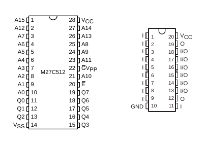
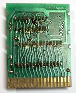
Michael Brutman provided me with two pictures of the cartridge internals:So it contain a 16L8 pal and what appears to be a 27C512 (64kB) EPROM. Here are the pinouts:

I can tell visually that at least the following address lines are connected to inputs on the PAL: A14, A13, A12, A11, A7, A6, A5. CS6 is also connected to pal pin 7 through the solder bridge. Pal I/O pins 12 and 19 are dedicated outputs. Those must be connected to the ROM enable (chip select and/or read) as well as the cartrige BASE2 to disable the internal PCjr BIOS ROM in the handled memory regions.
In any case, it appears that address decoding is done down to bit 5, which would mean a minimum stride of 32 bytes.
So only those ROM address ranges may be holding data.
- 08C0-08DF : No beep patch
- 0B80-0B9F : Fast memory test
- Possibly 1560-157F and 1580-15BF : Keyboard compatiblity fix
Thanks
Many thanks to Michael Brutman for providing the cartridge pictures, but also for his wonderful PCjr information website.Check out Mike's PCjr page at https://www.brutman.com/PCjr/pcjr.html.


