NES mods
- Why
- Remote reset button
- Stereo sound output
- Reprogrammable cartridge
- Disabling the lockout chip
- Blue power led
- Replacing the power supply
- Cartridge cleaning
- Restoring the cartridge connector
- Permanent game
- NES2 composite out mod
- Using SNES controllers on a NES
- Arcade style controller
- Playing arcade games
- Controller turbo-button mod
- Famicom light gun
- Disclaimer
Why
 Ah the NES! It's old but still great. And with a
few mods and tweaks, it can get even better.
Ah the NES! It's old but still great. And with a
few mods and tweaks, it can get even better.This page resumes some of the improvements or mods that can be done to a NES system.
Remote reset button
 I own a nintendo game cartridge named 260 in one, which is full of
fun games. The only drawback is that once you select a game, you must
reset the nes to return to the main menu.
I own a nintendo game cartridge named 260 in one, which is full of
fun games. The only drawback is that once you select a game, you must
reset the nes to return to the main menu.My NES console is near the TV, so when I want to change the game I have to get up and go to the other end of the room...
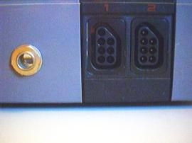
To fix this little problem, I have added a connector to my NES where I can connect a long wire to reset the NES remotely.
As you will see, it is very easy to do:
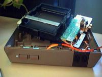 |
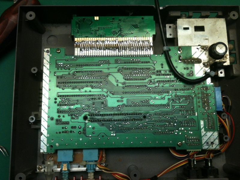
1) Open your NES and remove the metal sheet isolating the mother board. Also remove the motherboard. This is necessary to gain access to the small PCB where the Power and Reset buttons are located. |  |
2) You also need ot remove the reset/power PCB from the case, since you need to solder on the solder side of the PCB. |
 |
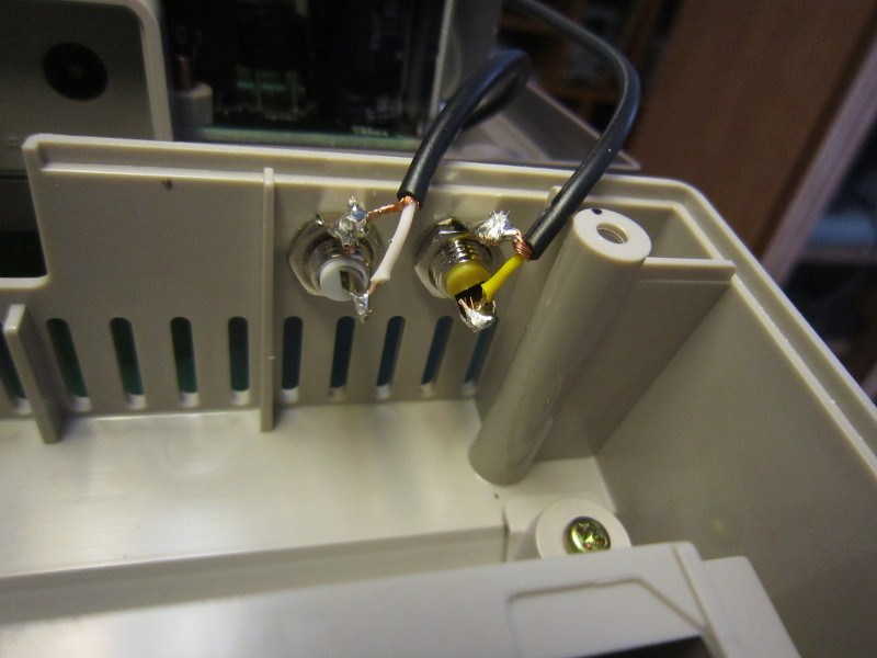
3) Solder your wires on the reset button. |  |
4) Install the connector on the case, and solder the wires coming from the reset button on it. |
As you can see, it is very simple. I used a 1/4 jack, as for headphones. The cable is so simple that I will not include pictures of it on this page. I did not install a button at the other end, I just touch the wires together.
The result:
Stereo sound output
 The NES has been designed to output mono sound. This
was acceptable back then, but nowadays we expect/need
stereo outputs. If you wish to connect your NES to a
stereo amplifier, you need an Y cable. You will hear
the same sound in both speakers.
The NES has been designed to output mono sound. This
was acceptable back then, but nowadays we expect/need
stereo outputs. If you wish to connect your NES to a
stereo amplifier, you need an Y cable. You will hear
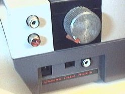
the same sound in both speakers.It is possible to do better by modding the NES to add "real" stereo sound. The NES CPU (2A03) has 2 sound outputs. One carries the 2 square wave channels and the other one carries the triangle wave channel, the noise channel and the sample channel. By tapping directly on the CPU pins (that is, before the mixing is done), it is possible to direct the 2 sound outputs to different speakers, thus obtaining stereo sound.
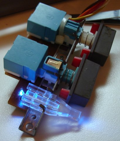
The knob on the picture is not a volume adjustment, it controls the stereo separation. The games were not designed for stereo, and it can be heard. Keeping a small amount (adjustable) of mono sound gives better results.
Here is a page containing detailed instructions (that's where I got the idea):
Since the original website does not work anymore, here is my schematic (different from the original):
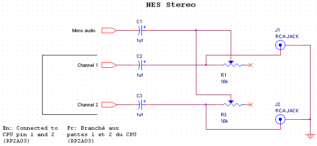
About the value for the potentiometer:
This mod has been described elsewhere, and the value used for the potentiometer is not always 10k.
Using a higher value potentiometer means a higher maximum resistance value. In theory, this means less mono sound and greater separation when the potentiometers are in the "maximum resistance" position.
That said, using a very high potentiometer (eg: 100k) would probably result in being able to hear mono sound for only a small area of the potentiometer range (eg: 1/8 of a turn), and increased adjustment sensitivity and difficulty.
The best approach is probably to experiment, starting with the potentiometers you have on hand, and decide what works best for your ears.
Here are a few pictures:
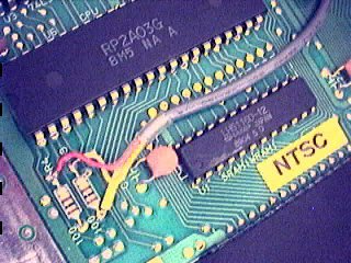
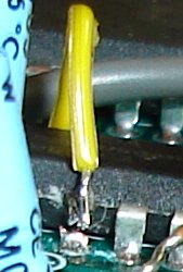
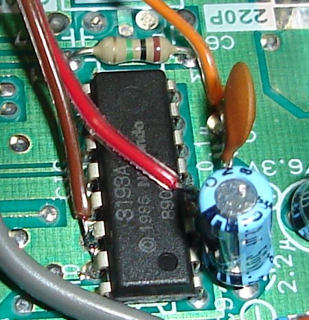
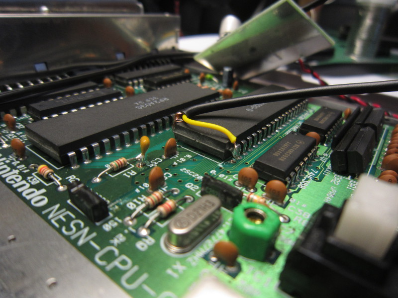
Connection on CPU
Mono pick-up
On the right: I tapped on one of the pins connecting the [power supply, RF modulator and RCA Mono audio/video output module] to get mono sound. Better be carful to use the right pin since there's the 12 Volts AC from the AC adapter on the same connector.

Cable routing
Reprogrammable cartridge
 This is not a mod on the NES itself, but it is on topic. I modified
a cartridge in a way that makes it reprogrammable.
This is not a mod on the NES itself, but it is on topic. I modified
a cartridge in a way that makes it reprogrammable.This project is on it's own page.
Disabling the lockout chip
(Based on the text 'Disabling the NES "Lockout Chip"', by Mark Knibbs)
 When nintendo designed the NES, they equipped it with a lockout chip. The main
reasons why they did this was (1) to prevent unlicensed companies to distribute their
own software and (2) make it harder to copy games. (Just imagine yourself buying
a game and reading in the manual that you must mod your NES in order to be able
to play!...). The chip also makes it impossible to play imported games.
When nintendo designed the NES, they equipped it with a lockout chip. The main
reasons why they did this was (1) to prevent unlicensed companies to distribute their
own software and (2) make it harder to copy games. (Just imagine yourself buying
a game and reading in the manual that you must mod your NES in order to be able
to play!...). The chip also makes it impossible to play imported games.How does the chip works?
The lockout chip is used in both the console and the cartridge. Depending on the logic level on pin #4, the chip will run in lock mode (console), or key mode (cartridge). When the NES is on, the chips normally try to communicate together using 3 signals. As long as the communication is not working correcly (no chip in cartridge or bad chip in cartridge), the lockout chip inside the NES will generate resets at 1 second intervals.
Why disable it?
- To be able to build your own NES cartridge without needing to remove the lockout chip from another cartridge.
- To be able to solder roms (or sockets) directly on the NES motherboard. (no cartridge and no lockout chip)
- To be able to use imported games without special adaptors.
- To be able to use unlicensed games which may have incompatible lockout chip immitations or even no chip at all


 All you need to do is put both chips in key mode. When both lockout chips are in key mode,
nothing happens (so no resets). To do this, you must disconnect lockout chip pin 4 from the
motherboard and connect it to a ground (lockout chip pin 11,12,13,14 or 15). It will also
work if pin 4 is not connected at all, so dont worry if you accidentally rip it off. Even though
it works without connection pin 4 to ground, I beleive it is better to do it anyway.
All you need to do is put both chips in key mode. When both lockout chips are in key mode,
nothing happens (so no resets). To do this, you must disconnect lockout chip pin 4 from the
motherboard and connect it to a ground (lockout chip pin 11,12,13,14 or 15). It will also
work if pin 4 is not connected at all, so dont worry if you accidentally rip it off. Even though
it works without connection pin 4 to ground, I beleive it is better to do it anyway.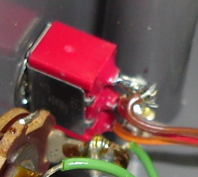
 I was a little worried that some cartridges would stop working due to this mod (cartridge with smarter
lockout chip?) so I added a switch to control the voltage on pin #4. I have not encountered such cartridges
yet, but the switch is there, just in case.
I was a little worried that some cartridges would stop working due to this mod (cartridge with smarter
lockout chip?) so I added a switch to control the voltage on pin #4. I have not encountered such cartridges
yet, but the switch is there, just in case.
Blue power led
 Nowadays, Blue leds are very trendy and are used everywhere. I tried to resist the temptation, but
couldn't. So that's right, I've replaced the boring red power led by a blue led, because "It's cool"!
Nowadays, Blue leds are very trendy and are used everywhere. I tried to resist the temptation, but
couldn't. So that's right, I've replaced the boring red power led by a blue led, because "It's cool"!
You simply unsolder the old led, and solder your blue led. In my case, I had a surface mount led so I soldered it on the old led's leads.

I bought the led from digikey. They have shipping and handling fees so if you only need one led, find a local electronic component store and buy the led from them.
Replacing the power supply
The original power supply is of the linear type, which means it uses a bulky transformer. This power supply has a few disadvantages:- It is bulky, which is not very convenient when you're carrying your NES in a pack sack.
- It covers almost 3 sockets when you plug it in a power bar.
- Mine is old and has started to fail (you need to pull the plug in the right direction to make it work!)
- It has an AC output, which is rarer. It is hard to find a perfect replacement.
 Switching power supplies are usually smaller than linear power supplies,
so I have used the switching power supply that came with my old cable modem. It
gives 12 volts up to 0.6 amps. So far, it has worked flawlessly with the NES.
Switching power supplies are usually smaller than linear power supplies,
so I have used the switching power supply that came with my old cable modem. It
gives 12 volts up to 0.6 amps. So far, it has worked flawlessly with the NES.
Cartridge cleaning
 So you have a game that does not start anymore? The screen repeatedly blinks? This
could be caused by a dirty NES cartridge connector or dirty cartridge contacts. Since it's
easier to clean the cartridge, it is better to try this first. If it does not work,
you might need to
restore the cartridge connector
inside the NES.
So you have a game that does not start anymore? The screen repeatedly blinks? This
could be caused by a dirty NES cartridge connector or dirty cartridge contacts. Since it's
easier to clean the cartridge, it is better to try this first. If it does not work,
you might need to
restore the cartridge connector
inside the NES.I will now show you how I clean my NES cartridges.
 1: First, I open the catridge. To complicate things, Nintendo used unusual screws. Here are a few
ways to remove them:
1: First, I open the catridge. To complicate things, Nintendo used unusual screws. Here are a few
ways to remove them:
- Buy the right tool. nintendorepairshop.com sells it.
- Take one or two small flathead screedrivers and try to use the notchs in the screw's head to unscrew it.
- I remember reading somewhere that you can heat the screws with a soldering iron and pull them out when the plastic starts melting. You use slightly bigger screws to close the cartridge.
- Use the force (not recommended)
- Build your own tool.


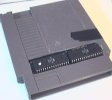
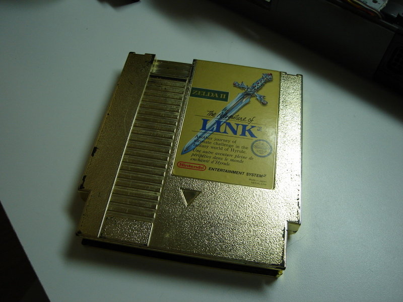
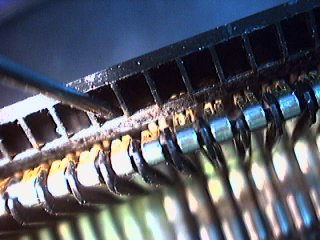
2: Once the cartridge is open, I inspect the connector. This one here is moderately dirty: (click for a close view)

 3: Cleaning
I scrub the contacts with an eraser until they are clean. Sometimes, they dont get perfectly clean, but there is always a great improvement. On the following picture, I have cleaned only the right half. We can clearly see the difference: (although the picture is not as good as I wanted it to be...):

While I have the cartridge open on my desk, I check the battery (if there is one):


Finally, I close the cartridge with ordinary screws so it will be easy to open in the future.
For reference: The tool to open the NES Power Pad is a gamebit 4.5mm screwdriver.
Restoring the cartridge connector
Idea from the text MAKE YOUR NES RUN BETTER THAN NEW!, by XBJ-9000
Blinking screen and non-working games? If cleaning your cartridge does not do it, you probaly need to restore or replace the internal cartridge connector.The cartridge connector inside the nes it very bad. The problem is that the metal contacts are applied to the cartridge PCB vertically instead of horizontally (which would move the dust and oxyde out of the way).
Fortunately, there is a way to fix this problem. You need to tweak the connector such that the contacts are closer together. There will be more friction when a cartridge is inserted and the fact that the contacts are more tightly pressed on the cartridge pcb will result in a more relable cartridge connector.
If you would prefer to replace the connector, you can buy one from the Nintendo Repair Shop.
Step 1:
Disassemble your nes and remove the cartridge connector.
Step 2:
Find a cloth pin and bend the tip.


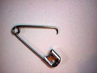
Step 3:
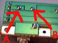
Using the pin, try to pull the contacts closer to the center. Do this for the upper row (the one near the square holes) and the bottom row.


Step 4: (optional)
A small flathead screwdriver can help to bend the upper contacts a little more:

Step 5:
The contacts should now be nearer to each other than they were before.
Left picture: before.
Right picture: after.

You dont need to do anything to the part of the connector which connects to the NES motherboard.
Reassemble your nes, and enjoy! The games should work pretty well now. They will even work without pushing the cartridge down!
Permanent game
If the cartridge connector of your NES is not usable anymore but the system otherwise works, you can hardwire a game by soldering wires between a cartridge and the NES motherboard. Say goodbye to flashing power LED problems, non-starging game, glitching games, but also to the ability to change game.

A few recommendations:
- Look at the cartridge PCB carefully and save time by not wiring unused contacts.
- Triple-check the orientation. Making a mistake is easy.
- Please don't use a rare or otherwise precious game cartridge.
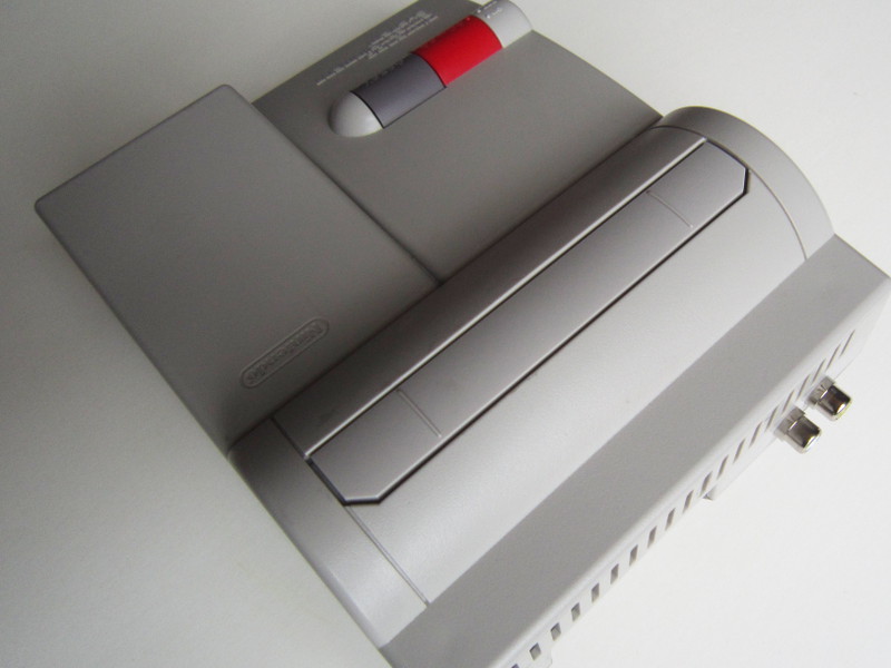
NES2 composite out mod
Nintendo did not think necessary to have a composite video output on the NES2 console. Also, there appears to be an interference problem on the PCB causing vertical stripes (see comparative pictures below) across the screen.I modified a NES2 console to capture the video signal directly at the PPU output pin. To reduce interference, I cut the pin so that it would not contact the PCB, but cutting the corresponding PCB track would also work. I also used coaxial cable for wiring.
To amplify the video signal before sending it to the TV monitor, I used my 3 Channel video buffer circuit.
Video signal

Audio signal

Power
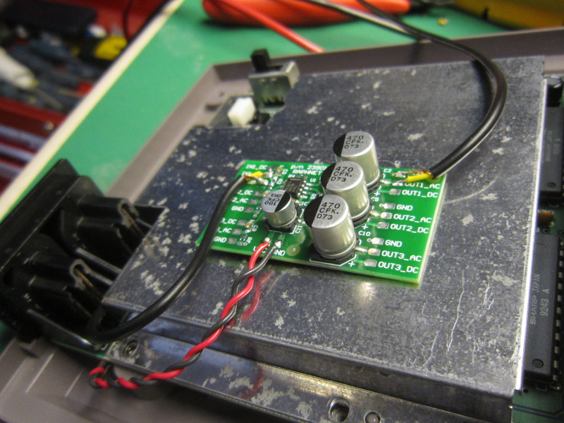
Buffer
RCA outputs

Overview
After the mod, the jailbars are almost gone. In fact, they are as faint as they were with the original NES.
Result

Result
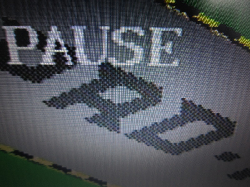
Before

After
Note that I am of course not the first to perform this modification. Here is another way to add a composite video output to a NES2 presented on gamesx.com: Adding A/V to a NES 2
Using SNES controllers on a NES
It has been known for a long time that using SNES controllers on a NES was possible and easy to do using simple wiring. So this is nothing new, but since I recently (2014) built such an adapter, I just thought I'd document it here.Anyone who has looked at how SNES and NES controllers work knows that those are simple shift registers. A button state snapshot is first taken using the LATCH signal. The bits corresponding to each button are then transmitted serially on the DATA line, at a pace controlled by the CLOCK signal. As SNES controllers have more buttons than NES controllers, an SNES console has to send 12 to 16 clock pulse to read all buttons while a NES console only sends 8 pulses.
Since the first 8 SNES button states are transmitted in an order compatible with the NES, using an SNES controller on a NES is a simple wiring matter. The additional SNES buttons simply won't be read and therefore won't be usable. (Though in theory, one could write a NES game with SNES controller support)
| Clock cycle | SNES Button | NES Button |
|---|---|---|
| 1 | B | A |
| 2 | Y | B |
| 3 | Select | Select |
| 4 | Start | Start |
| 5 | D-pad up | D-pad up |
| 6 | D-pad down | D-pad down |
| 7 | D-pad left | D-pad left |
| 8 | D-pad right | D-pad right |

SNES controller to NES wiring
Notice how the SNES B/Y maps to NES buttons A/B. It might seem wrong at first that the B and A buttons be swapped, but it is in fact exactly what's needed given the physical button layout. For instance, in the NES Super Mario, B=run, A=jump. In Super Mario World on the SNES, Y=run, B=jump. So when playing Super Mario on the NES using an SNES controllers, Y=run, B=jump. It feels perfectly natural.
Here a picture of an adapter I built using an SNES and NES extension. The wires were soldered and then insulated using heat-shrink tubing.

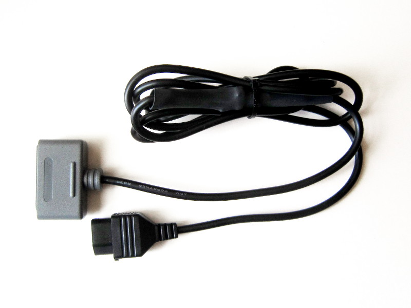
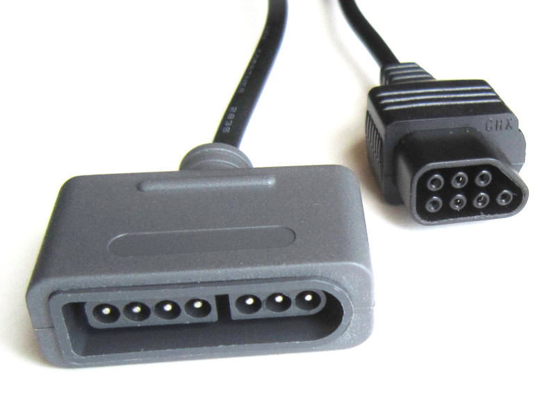
Warning: Do NOT rely on the wire colors shown in the above pictures. The relationship between pin numbers and wire color varies according to the cable manufacturer, and sometimes even between batches. You must find out the color code used by your cables using a continuity tester. Blindly following the colors seen here may damage your NES or SNES controller.
Note: This adapter works on the NES, but also on the AV Famicom which has the same type of connector for controllers.
If you are looking for a ready-made adapter, you can buy one from my online store.
Arcade style controller
 Games feel different when played with an arcade style controller. Also, if you
are playing arcade game ports, you will get a more authentic gameplay.
Games feel different when played with an arcade style controller. Also, if you
are playing arcade game ports, you will get a more authentic gameplay.Please visit my Arcade style controller for Snes, Nes and PC page for instructions to build one yourself.
Playing arcade games
 I modified a NES to be able to play old Nintendo arcade roms on it. This
project is quite complex so it has
it's own page.
I modified a NES to be able to play old Nintendo arcade roms on it. This
project is quite complex so it has
it's own page.
Controller turbo-button mod
I have been asked how one could add turbo buttons to a regular controller. I don't have the time to do it, but here is what I suggest if using a micro-controller must be avoided. (Sincerely, it would be quicker for me just to grab one of my multiuse pcb2 boards and write a special firmware).A turbo button running at 30hz could be done like this:
		Add a CD4013 D type flip flop. Clock it using the latch
		signal from the NES. Route the inverted output to the data
		input so on each clock edge the output toggles between high
		and low.


		The non-inverted output of this flip flop would then go
		to each of your turbo buttons, which, when pushed, would
		pull the non-gnd side for the button being turbo'ified to
		GND through a transistor.


		The CD4013 chip contains two flip flops so you could chain
		them to slow down the turbo to 15Hz if 30Hz is too high.


		I did a quick research to find an example circuit which
		could somehow clarify what I wrote above, and this comes close.
		Of course, you would use the 5v supply
		available in the NES controller, and no relay.

		http://www.zen22142.zen.co.uk/ronj/tg1s.html


		Another approach would be to use the famous 555 IC. A variable
		resistor could then control the rate of the Turbo. The 555 output
		would be distributed to the turbo buttons as explained above.
Note: If you mod a controller using the technique outlined above, please let me know and send me pictures to add here!
Famicom light gun
An adapter to use a Famicom light gun (Basically, a Zapper that looks more like a real gun) can be built using the following wiring:| Signal name | DB15 pin | NES pin |
|---|---|---|
| GND | 1 | 1 |
| VCC | 15 | 5 |
| D3 | 5 | 6 |
| D4 | 4 | 7 |

Note: Many NES extension cables are meant only for controllers and do not wire pins 6 and 7! If you have no other choice, a Zapper can be sacrified for its cable.
Disclaimer
I cannot be held responsible for any damages that could occur to you or your equipment while following the procedures present on this page. Also, I GIVE ABSOLUTELY NO WARRANTY on the correctness and usability of the informations on this page. Please note, however, that the procedures above have worked in my case without any damages or problems.Now you cannot say that I did not warn you :)