Foot pedal input adapter for Wii guitar
What this is about
Wii guitars (some? all?) have a port supporting an external switch. I'm not sure what this port was meant for, but my adapter design (sold here) supports this input as an extra button since firmware 2.2.3.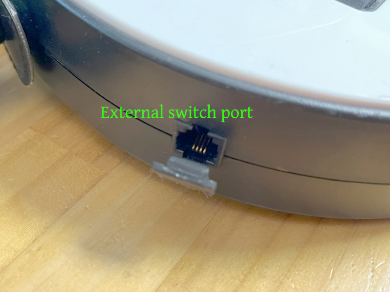
The port on the guitar
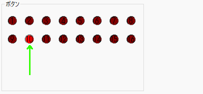
The state of the external switch is reported through button 10:
As I have been asked a few times for information about how to use this port, I decided to create this page to explain how one can use it.
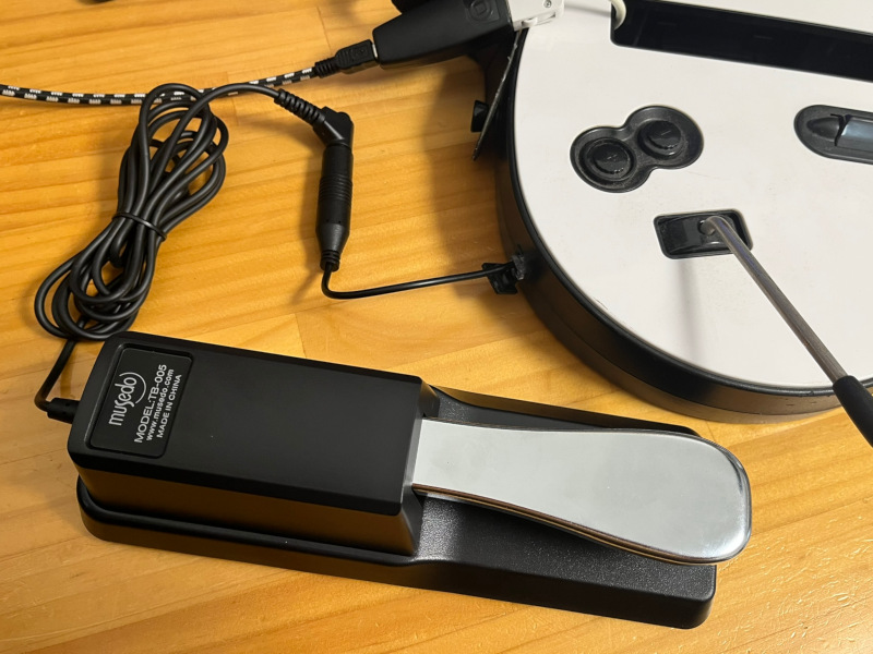
Pedal connected and ready to play!
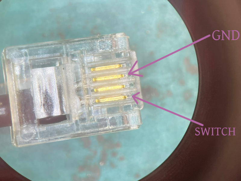
Connector pinout
The connector used on the guitar is a 6P4C (6 positions, 4 contacts) modular connector as typically used by telephony equipment.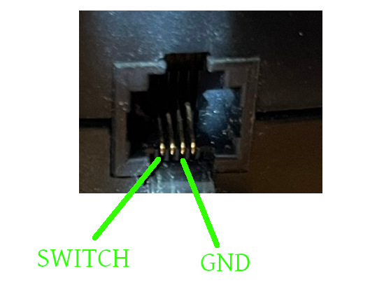
A momentary switch (such as a pedal) simply needs to be wired to the two pins indicated above.
Choosing a pedal
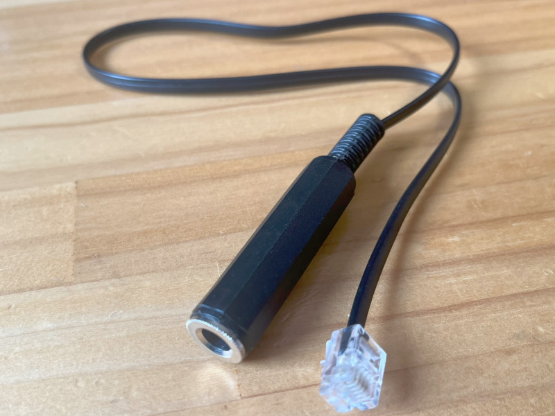
A wide choice of cheap pedals meant to be used with electronic pianos is available online. Usually, the connection is a large 1/4" jack (big headphones jack).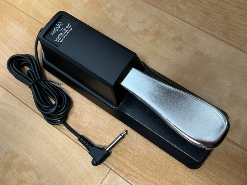
Generic pedal
Those pedals normally only contains a simple electrical switch, but two wiring circuit styles exist:
- Normally closed circuit (aka NC or N.C.)
- Normally open circuit (aka. NO or N.O.)
Generic pedals (i.e. those that are not meant for a specific brand of keyboard) often support two wiring styles selectable using a small switch somewhere on the pedal body.

NO/NC switch on pedal
If on the PC side you see that button 10 is active as soon as you connect the pedal, and that button 10 turns off when you push down on the pedal, then the pedal is operating in "normally closed" mode. Change the switch to the "Normally open" position. As a last resort, if there is no such switch on your pedal, it may be possible to rewire it. If the internal switch has 3 poles, moving the wire from the "NC" to the "NO" pole should do the job.
Example build without soldering (6P4C Crimping)
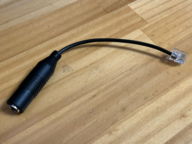
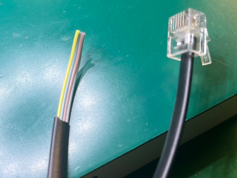
If you have the necessary tools for crimping 6P4C connectors, and (it would help) also a bit of experience crimping Ethernet cables (Ethernet 8P8C crimp tools often have an additional opening for 6 pin connectors), you can build a pedal adapter by cutting a headphones extension and crimping a 6P4C connector at the end. No soldering is required for this construction technique.For instance, a cable like this can be used:
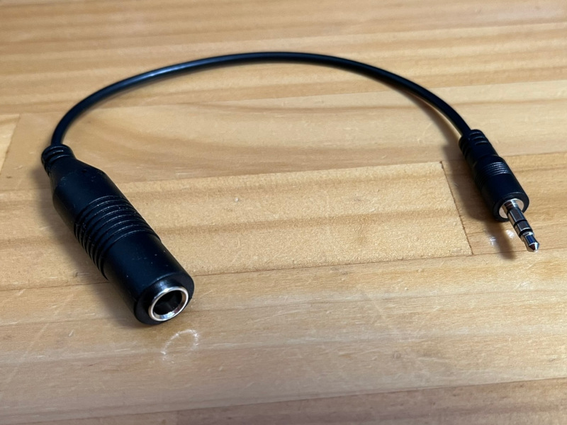
Example donor cable
Adequate tuning of the wire length (and stripping if the diameter is too large for the 6P4C connector) as well as stripping just enough of the cable external sheath is crucial for reliable results and making sure the cable does just fall out at a light pull...
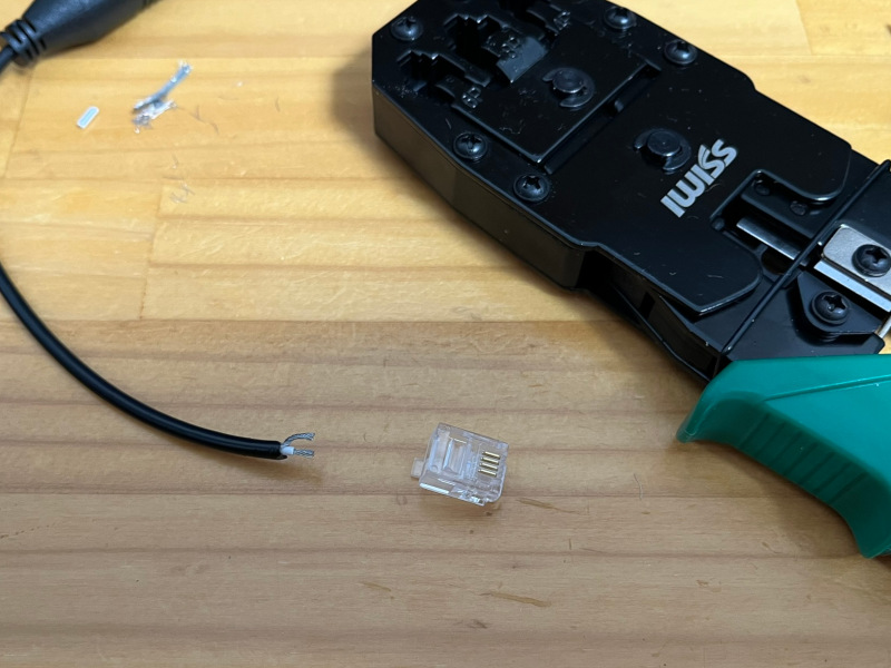
Getting ready to crimp
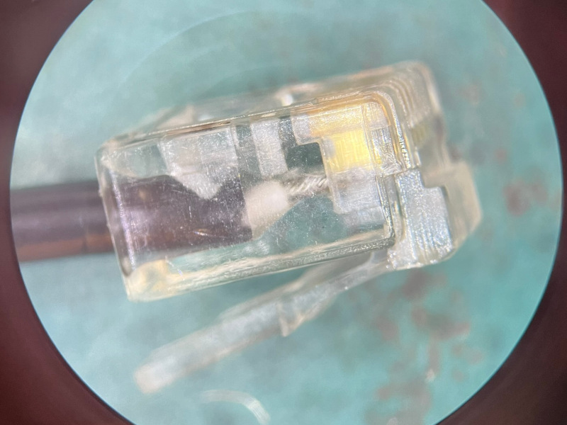
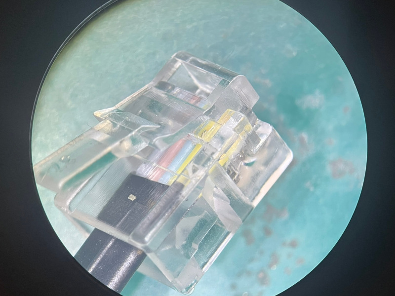
Crimped connector close up (side)
Crimped connector close up and pinout (top)
Resulting adapter
Ready to play!
If you do not plan to use the pedal for anything else, just cutting the pedal cable and crimping a 6P4C connector directly is also an option to consider!
Exemple build with soldering
If you can solder, building a cable should be easy. Find a 6P4C telephone cable, cut it, and solder the wires to an inline 1/4" audio connector.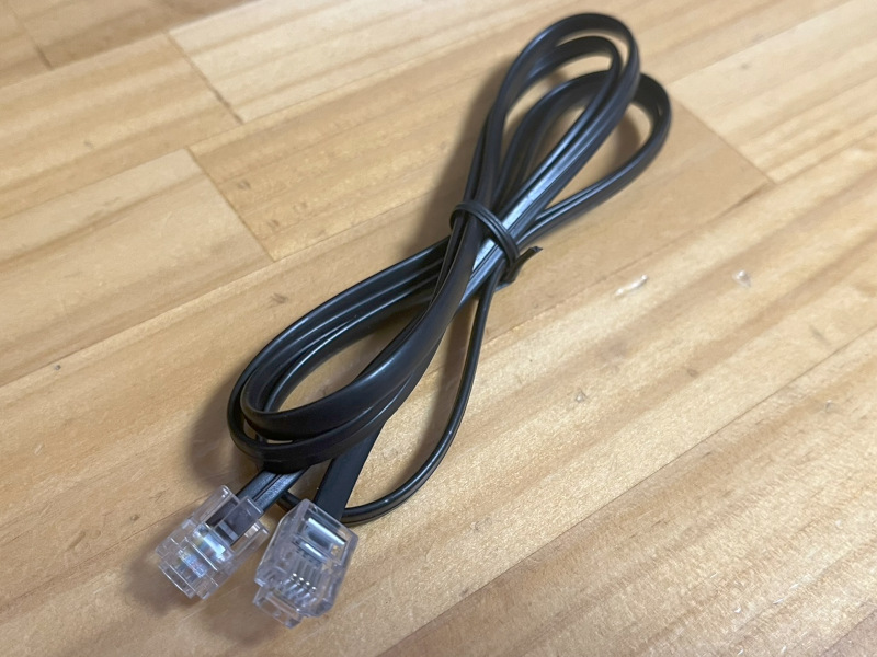
Example 6P4C cable
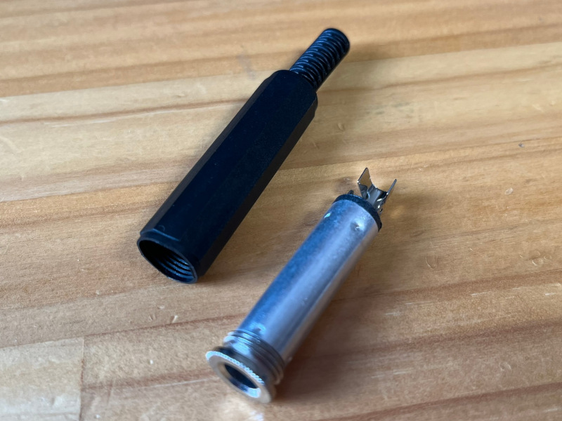
Exemple 1/4 inch connector
Look closely at the transparent 6P4C connector and identify which wire color correspond to the two target pins on the guitar connector. Cut the cable in half, strip it and cut the unused wires.
Identification des couleurs
Câble coupé
Next solder the wires to the 1/4" connector pins.
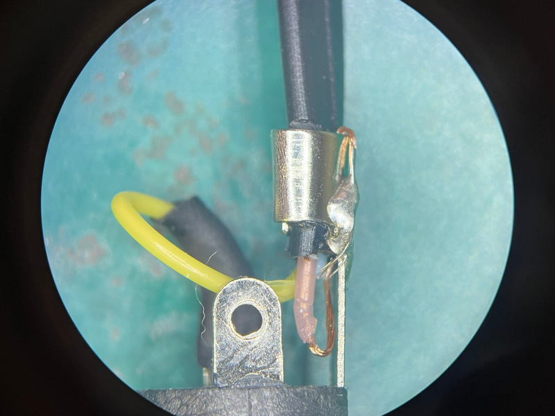
Soldering example
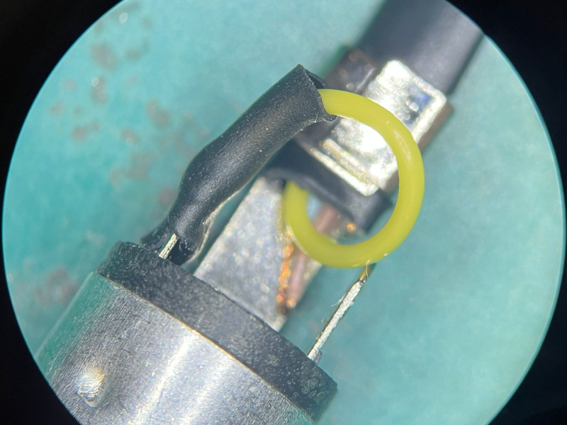
Soldering example
All done!
Adapter ready to use
Wiring a tile sensor
Instead of wiring a foot pedal, wiring a tilt switch is also an interesting use of this port. Installed at the correct place and angle on the guitar, the tilt switch can be triggered by tilting the guitar upwards.Building this from a 6P4C phone cable or extension (as shown in the previous section) is a simple matter of wiring the two tilt switch pins.
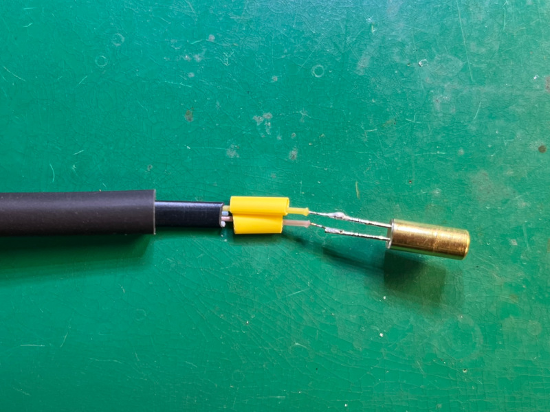
Soldering done
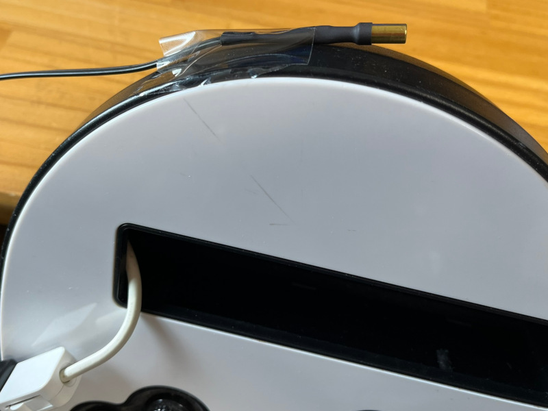
Installed on guitar (example)
Disclaimer
It's probably obvious, but never connect the guitar to a phone line! Never connect a pedal to a phone line! ;-)I cannot be held responsible for any damages that could occur to you or your equipment while following the procedures present on this page. Also, I GIVE ABSOLUTELY NO WARRANTY on the correctness and usability of the informations on this page. Please note, however, that the procedures above have worked in my case without any damages or problems.
Now you cannot say that I did not warn you :)